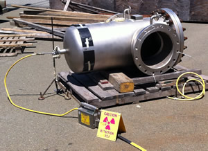
 Radiographic Testing (RT)), or industrial radiography, is a nondestructive testing (NDT) method of inspecting materials for hidden flaws by using the highly penetrating electromagnetic waves such as X rays or Gamma rays. These radiations are of short wavelength electromagnetic radiation (high energy photons) which can penetrate in to various materials. Either an X-ray machine or a radioactive source (Ir-192, Co-60, or in rare cases Cs-137) can be used as a source of photons. Since the amount of radiation emerging from the opposite side of the material can be detected and measured, variations in this amount (or intensity) of radiation are used to determine thickness or composition of material. Conventional Radiography uses the Film as the source of recording media and advanced /Digital radiography uses advanced digital recording technology.
 Ultrasonic Testing (UT) uses high frequency sound energy to conduct examinations. Ultrasonic inspection can be used for flaw detection/evaluation, dimensional measurements, material characterization, and more. The Ultrasound energy is generated using Piezo Electric Principle and introduced in the part being inspected, which can propagates through the materials in the form of waves. When there is a discontinuity (such as a crack) in the wave path, part of the energy will be reflected back from the flaw surface which was received and analyzed to know the nature and dimensions of the discontinuity. Ultrasonic Inspection is a very useful and versatile NDT method. Some of the advantages of ultrasonic inspection that are often cited include:
 Magnetic Particle Inspection (MPI) is a non-destructive testing method used for defect detection. Magnetic flux leakage is the Basic Principle used in this technique. MPI is fast and relatively easy to apply. Surface preparation is not as critical as it is for some other NDT methods. MPI uses magnetic fields (Electromagnetic filed mostly) and small magnetic particles (i.e. iron filings) to detect flaws in components. The only requirement from an inspect ability standpoint is that the component being inspected must be made of a ferromagnetic material such as iron, nickel, cobalt, or some of their alloys. Ferromagnetic materials are materials that can be magnetized to a level with an external magnetizing force that will allow the inspection to be effective.
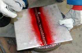 Liquid Penetrant Testing or Dye Penetrant Testing is a method that is used to reveal surface breaking flaws by bleed out of a colored or fluorescent dye from the flaw. The technique is based on the ability of a liquid to be drawn into a “clean” surface breaking flaw by capillary action. After a period of time called the “dwell,” excess surface penetrant is removed and a developer applied. This acts as a blotter. It draws the penetrant from the flaw to reveal its presence. Colored penetrants require good white light while fluorescent penetrants need to be used in darkened conditions with an ultraviolet “black light”. The advantage that a liquid penetrant inspection (LPI) is that it makes defects easier to see for the inspector. LPI produces a flaw indication that is much larger and easier for the eye to detect than the flaw itself. Many flaws are so small or narrow that they are undetectable by the unaided eye. Highly sensitive to Surface cracks and technique is applicable for all materials except Porous.
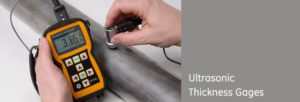 Ultrasonic thickness measurement (UTM) is a non-destructive measurement (gauging) of the local thickness of a solid element (typically made of metal, if using ultrasound testing for industrial purposes) basing on the time taken by the ultrasound wave to return to the surface. This type of measurement is typically performed with an ultrasonic thickness gauge. UTM is frequently used to monitor metal thickness or weld quality in industrial settings. With portable UTM probes measurement can be made steel plating in sides, tanks, decks and the superstructure. They can read its thickness by simply touching the steel with the transducer. Advantages:
 Visual Inspection is a Basic NDT method to be used for each and every component before it is used for fabrication or installation or usage. It is the most common method of quality control, data acquisition, and data analysis. Visual Inspection, used in maintenance of facilities, mean inspection of equipment and structures using either or all of human senses such as vision with normal aids. Visual Inspection typically means inspection using raw human senses vision and/or any non-specialized inspection equipment.It constitutes an important aspect of practicable quality control for weldments with joints that require testing. It has been proven in numerous situations that an effective programme of visual inspection will result in the discovery of the vast majority of those defects which would be found later using some other more expensive non-destructive test methods.
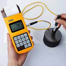 Hardness is the measure of how resistant solid matter is to various kinds of permanent shape change when a force is applied. However, the term hardness may also refer to resistance to bending, scratching, abrasion or cutting. Macroscopic hardness is generally characterized by strong intermolecular bonds, but the behavior of solid materials under force is complex; therefore, there are different measurements of hardness: scratch hardness, indentation hardness, and rebound hardness. Hardness is dependent on ductility, elastic stiffness, plasticity, strain, strength, toughness, viscoelasticity, and viscosity The usual method to achieve a hardness value is to measure the depth or area of an indentation left by an indenter of a specific shape, with a specific force applied for a specific time. There are three principal standard test methods for expressing the relationship between hardness and the size of the impression, these being Brinell, Vickers, and Rockwell. Features of portable Hardness tester:
 Heat Treatment is a group of industrial and metalworking processes used to alter the physical, and sometimes chemical, stress relieving, and other properties of a material. The most common application is metallurgical. Heat treatment involves the use of heating or chilling, normally to extreme temperatures, to achieve a desired result such as hardening or softening of a material. Heat treatment techniques include annealing, case hardening, precipitation strengthening, tempering and quenching. It is noteworthy that while the term heat treatment applies only to processes where the heating and cooling are done for the specific purpose of altering properties intentionally, heating and cooling often occur incidentally during other manufacturing processes such as hot forming or welding. Pre weld heat treatment and post weld heat treatment for stress relieving most commonly used during fabrication. Pre Weld Heat treatment When welding some base materials and for some service conditions, preheating and/or post weld heat treatment may be a requirement. These types of thermal treatments are generally required in order to ensure suitable weld integrity and will typically prevent or remove undesirable characteristics in the completed weld. Any form of heat treatment is costly since it demands extra equipment, extra time, and extra handling. For these reasons, heat treatment should only be undertaken after careful consideration of the advantages it may offer. In certain cases heat treatment will be mandatory, as with heavy sections of low alloy steels, whereas in other cases, it will be a justifiable precaution against early failure in service. Preheating during Welding provides the following benefits:
Post Weld Heat Treatment Post Weld Heat Treatment Services is defined as the stress relieving method after welding to improve the mechanical and chemical properties of welds. There are different ways of performing PWHT like local heat treatment and furnace heat treatment. We have skilled and highly experienced personnel available to perform Heat Treatment. Machining and/or Welding induce stresses in parts. The bigger and more complex the part, the more the stresses. These stresses can cause distortions in the part in long term. If the parts are clamped in service, then cracking could occur. Also whole locations can change causing them to go out of tolerance. For these reasons, stress relieving is often necessary.
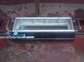 Vacuum Box Testing is used to check for any leaks or fault in the welding of bottom & annular plates of the storage tank. The vacuum pump attached creates a vacuum in the vacuum box, which shows bubbles on the soap water applied on the weld in case of any leaks or faults. This is one of the most adoptive test methods to detect leak or defects and widely used in the bottom plate of Tank, Ships & barge bottom plates etc
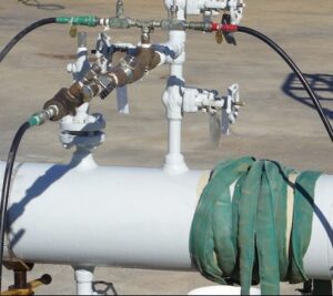 Hydrostatic (Hydro) Testing is considered to be a nondestructive testing method; A hydrostatic test is performed to determine the integrity and soundness of piping systems, gas cylinders, boilers, pressure vessels and fuel tanks. A decrease in the applied pressure or leakage through the products or joints or plastic deformation or distortion or bulging in the product is indication of inadequate quality of the product under test. This test method is also termed as Leak testing (based on the principles of leakage during pressurized condition) and Pressure Drop Test (based on the principles of decrease in pressure during test due to unacceptable discontinuities). It is also the most common method often employed and it is the one of the most reliable test methods when determining the integrity and soundness. Hydrostatic (Hydro) Testing is a type of pressure test that works by completely filling the component with water, removing the air contained within the unit, and pressurizing the system up to 1.5 times the design pressure limit of the unit. The pressure is then held for a specific amount of time to visually inspect the system for leaks. This test is preferred over pneumatic test due to safety reasons. Hydrostatic test method is applied on the newly manufactured pressure equipment’s, after alterations, repairs and before re-commissioning stage.
 Holiday Test or a Continuity Test is one of the non-destructive test method applied on protective coatings to detect unacceptable discontinuities such as pinholes and voids. The test involves checking of an electric circuit to see if current flows to complete the electrical circuit. A Holiday test or Continuity test is performed by applying low voltage (connected in series with an LED or noise-producing component such as a piezoelectric speaker) across the chosen path. If the electrical flow is detected then the test area is termed as conductive indicating presence of discontinuities such as pinholes and voids.
 Coating thickness is an important variable that plays a role in product quality, process control, and cost control. Measurement of film thickness can be done with many different instruments. Understanding the equipment that is available for film thickness measurement and how to use it is useful to every coating operation. The issues that determine what method is best for a given coating measurement include the type of coating, the substrate material, the thickness range of the coating, the size and shape of the part, and the cost of the equipment. Commonly used measuring techniques for cured organic films include nondestructive dry film methods such as magnetic, eddy current, ultrasonic, or micrometer measurement and also destructive dry film methods such as cross-sectioning or gravimetric (mass) measurement. Methods are also available for powder and liquid coatings to measure the film before it is cured.
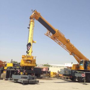 Load testing is the process of putting demand on and measuring its response. Load testing is performed to determine a system’s behavior under both normal and anticipated peak load conditions. It helps to identify the maximum operating capacity of an application as well as any bottlenecks and determine which element is causing degradation. When the load placed on the system is raised beyond normal usage patterns to test the system’s response at unusually high or peak loads, it is known as stress testing. The load is usually so great that error conditions are the expected result, but there is no clear boundary when an activity ceases to be a load test and becomes a stress test.
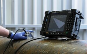 Phased Array Ultrasonic testing (PAUT) enables the generation and receiving of an ultrasonic beam where parameters such as angle, focal distance, and focal point size are controlled through software. The ultrasonic beam can be multiplexed over a large array. The wide range of capabilities Provides greater feasibility to the user in using PAUT. For instance, it is possible to quickly vary the angle of the beam to scan a part without moving the probe itself. Phased array also allows replacing multiple probes and mechanical components. Inspecting a part with a variable-angle beam also maximizes detection regardless of the defect orientation, while optimizing signal-to-noise ratio. Semi-Automated inspection and Data recording provides additional support to replace PAUT in place of RT. Major Applications:
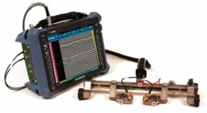 Time of Flight Diffraction (TOFD) works with the Principle of diffraction in contrast to Reflection of ultrasound as used in conventional UT. The deflection of a wave front as it passes an ultrasonically opaque object and expands into the region that is behind the object and hence not directly exposed to the incoming waves. When ultrasound is incident at linear discontinuity such as a crack, diffraction takes place at its extremities. The study of this phenomenon has led to the use of time of flight diffraction method of crack sizing. TOFD is very sensitive to detecting all kinds of defects, irrespective of its orientation. Using this advanced technique gas, binding defects, porosity, slag inclusions and cracks can be detected independent of defect orientation with very accurate sizing of the defects. Advantages & applications of TOFD :
Company that offers wide range of Services & Products to Industrial, Commercial & Government Clients across Petrochemical, Process plant, Oil & Gas, Marine, Cement and Power Sectors.